Mag Loop First Try
I had the great fortune to spend some time with Amy Herndon (AI6ZU) and Jeri Ellsworth (AI6TK) at the Dayton Airport after Hamvention. Lots of radio nerding happened – lots! At one point, I commiserated that I'd never bothered trying HF (roughly 3 to 30 MHz) ham radio because I live in an dense residential area, near an airport, with lots of above-ground power and communications lines. They quickly disabused me of my assumptions and described how effective magnetic loop antennas are in noisy, urban environments. They also pointed out how easy they are to build. In fact, they made a video on the subject a while back! Their enthusiasm for mag loop antennas motivated me to try building one myself.
I read up a bit on magnetic loop antennas. Steve Yates (AA5TB) has a great write-up with a spreadsheet calculator. I was impatient and went straight to the spreadsheet. After a few minutes of playing with the numbers, it became obvious that your loop diameter can be smaller if your conductor diameter is larger. 12-gauge copper would be too thin to have an efficient antenna that I could build indoors (less than 2m diameter). That was a shame, as I have a LOT of 12-gauge wire left over from the Church of Robotron at ToorCamp 2012. I needed something thicker! The thickest conductor I could find was some RG/58 coaxial cable I bought for cheap from a Radio Shack store that was closing. RG/58 has an outer diameter of about 5mm (0.2"). I'd use the shield as the conductor, and ignore the center conductor. Putting that diameter into the calculator, a 2.17m (7.1') diameter loop at 10.1MHz would be 60% efficient. Good enough for a first attempt!
The design would need a tuning capacitor of about 30.5pF. Somewhere, long ago, I acquired dozens of little trim capacitors. One of them had the range I needed. I used a capacitance tester to pre-tune the capacitor to the value the spreadsheet recommended. I stripped and zip-tied the two ends of my coax together, and soldered the trim capacitor between the shields of the two ends of the coax. I then draped the loop over a window curtain rod at one side of the room, and a door on the other side. The shape wasn't so much a magnetic "loop" as it was a magnetic "banana".
Then there was the matter of coupling the signal from the loop into a 50 Ohm coaxial cable that would go to my receiver. Another great write-up discussed transformer coupling options. Since I had a ferrite toroid, and a BNC to dual binding post adapter laying around, I decided to use that approach. I passed the loop cable through the toroid, and then ran a bit of insulated solid copper wire through as well, terminated at either end by the BNC-binding adapter. The transformer coupling is supposed to be at a point 180 degrees opposite of the tuning capacitor, but I didn't bother to measure. I just located it where it seemed about right.
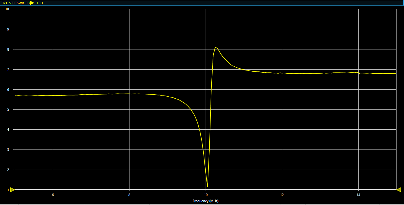
I hooked this janky contraption up to my antenna analyzer and…

…What? First try? Nailed it! That was too, too easy.

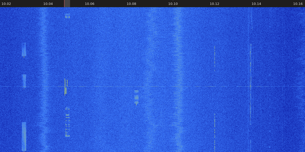
I tuned around a bit, and found a bunch of different signals. Most of them were digital, likely RTTY, FT8, JT65 and so on. But there was a bit of faint Morse and SSB voice chatter too. And WWV in Fort Collins, Colorado was coming in great! I'll have to spend some time with the Signal Identification Wiki and see what else I can recognize.
So what did I learn? Magnetic loop antennas work well in urban settings, inside houses, are easy to build, and seem pretty tolerant of my terrible construction practices! I'm hooked, and will certainly be building more and better magnetic loop antennas soon! ToorCamp/Field Day are coming up soon!